
What are the Factors Determining Waveplate Retardation Tolerance
Overview:
This article provides a comprehensive overview of several factors that affect waveplate retardation tolerance.
What is waveplate retardation/phase delay?
For waveplates , reatardation, sometimes called retardance or phase delay, refers to the phase difference between the two perpendicularly polarized components of light after it passes through the waveplate.
The core function of a waveplate is to control the polarization state of incident light by using the phase difference between the two perpendicularly polarized components.
For example, a quarter-wave plate can be used to convert between circularly polarized and linearly polarized light, while a half-wave plate can be used to rotate the angle of linearly polarized light.
Mechanism of waveplate retardation generation:
The following is a detailed explanation of how phase delay is generated in a waveplate: Phase delay in a waveplate refers to the phase difference between two orthogonal polarization components, namely the ordinary (o) ray and the extraordinary (e) ray, resulting from the birefringence of the birefringent crystal used to manufacture the waveplate after light passes through it.
By designing the material and thickness of the waveplate, a pre-designed phase delay (e.g., a quarter-wave plate and a half-wave plate) can be generated to manipulate the polarization state of light.
In a birefringent crystal, any incident light beam will be "decomposed" into two light components with mutually perpendicular (orthogonal) polarization states and different propagation speeds: the o-ray and the e-ray.
Ordinary light (o-ray): follows Snell's law of refraction, its propagation speed is independent of direction, and its refractive index is constant.
Extraordinary light (e-ray): does not follow Snell's law of refraction, its propagation speed varies with direction, and its refractive index depends on the angle between it and the optical axis.
Birefringence arises from the anisotropy of atomic arrangement within a crystal, causing the dielectric constant to vary with direction, which in turn leads to differences in light propagation properties.
For example, in a uniaxial crystal, the wavefront of the o-ray is a sphere, while the wavefront of the e-ray is a spherical ellipsoid.
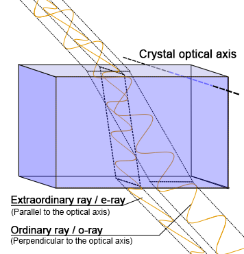
Figure 1. Birefringence of crystals
Waveplates are manufactured by processing birefringent crystals such as quartz, calcite, or mica into wafers of precise thickness, ensuring the light -transmitting surface is parallel to the crystal's optical axis.
In other words, the direction of propagation of the incident light is perpendicular to the crystal's optical axis.
This is because if the direction of propagation of the incident light is not perpendicular to the crystal's optical axis, the two beams of light will separate in space and cannot be synthesized.
By using the cutting and application method of "light-transmitting surface parallel to the optical axis and normal incidence," a single beam of light can be obtained that merges along its spatial path, while the two orthogonally polarized states have a phase difference.
Let's consider the case where the incident light is linearly polarized.
Assume the angle between its vibration direction and the optical axis of the waveplate is θ.
The incident light vibration is decomposed into two components: one perpendicular to the optical axis and the other parallel to it (e-vibration), corresponding to the ordinary and extraordinary rays in the crystal, respectively.
The two components are in phase when incident on the waveplate.
However, because the two mutually perpendicular polarization components propagate at different speeds in the crystal (speed v = c / n, where c is the speed of light in vacuum and n is the refractive index; the component with the slower propagation speed has a larger refractive index n), after traveling the same distance (i.e., the thickness of the waveplate) within the waveplate, the two components have different optical path lengths, resulting in an additional phase difference when exiting the waveplate.
What are fast axis and slow axis?
A key concept in waveplates is the fast axis and the slow axis. What are the fast and slow axes?
The slow axis is the axis with a higher refractive index, corresponding to a slower propagation of light components.
The fast axis is the axis with a lower refractive index, corresponding to a faster propagation of light components.
For example, for a quartz waveplate, nₑ < nₒ, so the e-axis is the fast axis and the o-axis is the slow axis.
Waveplate holders manufactured by Shalom EO will have the fast axis marked as a straight line, as shown in the image below:
What’s the mathematical formula of retardation of waveplates?
The relationship between the phase delay produced by a waveplate and the waveplate thickness and the refractive index of the waveplate material can be calculated using the following formula:
The optical path difference between the o-ray and e-ray in the waveplate is:
Δ P= ∣Pno-Pne∣ = d∣ne-no∣
ΔP is the optical path difference, d is the waveplate thickness, ne is the extraordinary refractive index, and no is the ordinary refractive index.
The phase delay produced by the waveplate is:
Φ = 2*π/2*d∣ne-no∣
Φ is the phase difference, d is the waveplate thickness, ne is the extraordinary refractive index, no is the ordinary refractive index, and d|ne-no|
is the optical path difference.
What is the retardation accuracy/retardation tolerance?
The reatardation accuracy, or equally called retardation tolerance, of a waveplate refers to the degree of deviation between the actual phase delay produced by the waveplate and the ideal value (such as λ/4, λ/2, etc.).
It directly determines the accuracy of the waveplate in controlling the polarisation state of light.
Generally, waveplate suppliers will specify the phase delay error in the waveplate specifications.
For example, the phase delay error of the Shalom EO’s air-spaced zero-order waveplate is:
λ/60-λ/200 (λ<400nm) ;
λ/200-λ/400(400nm<λ<700nm) ;
λ/400-λ/600 (λ>700nm) ;
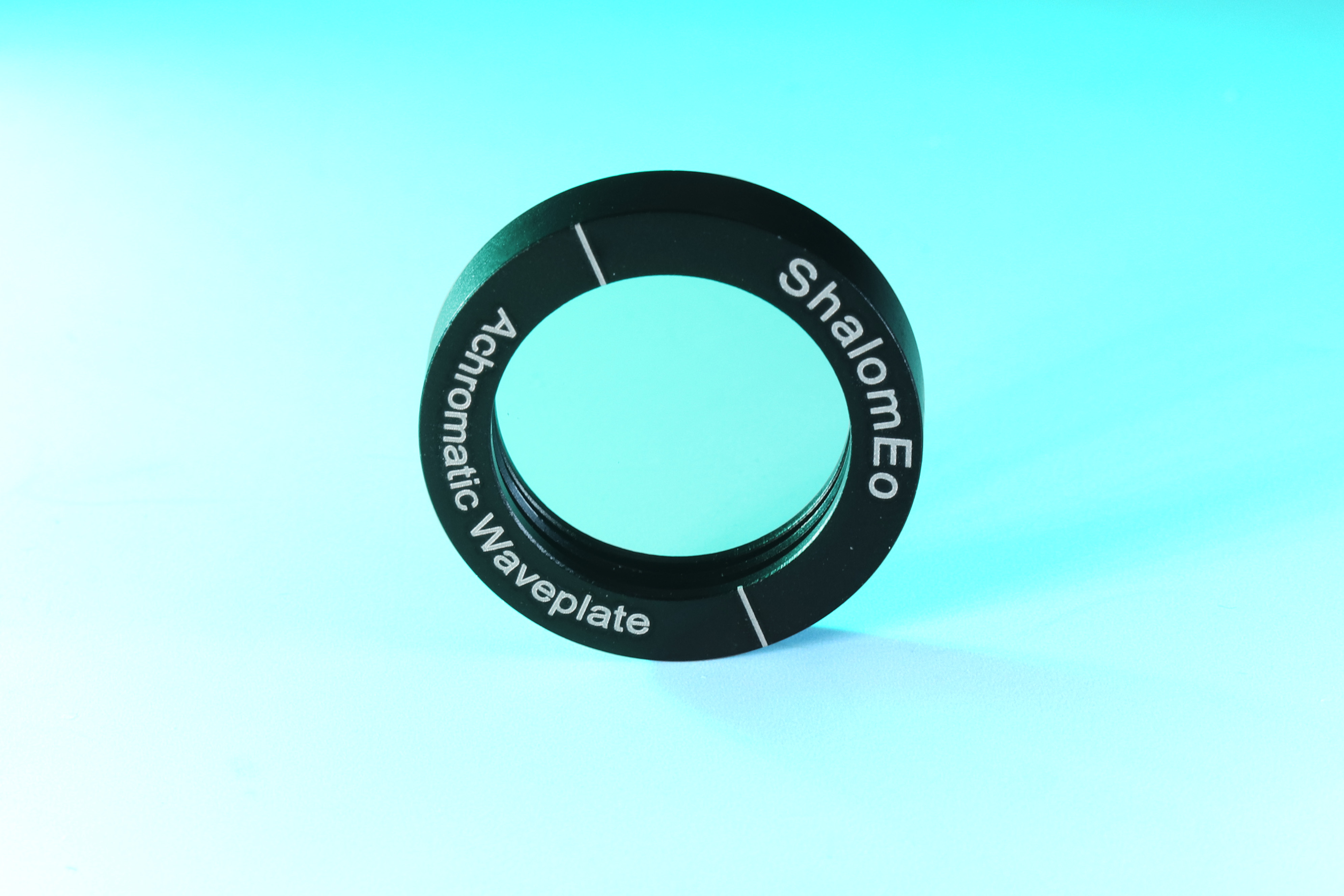
Figure 2: Shalom EO’s waveplate
From the phase delay formula above, we can intuitively see that the phase delay of a waveplate is directly related to the waveplate thickness and the refractive index (ne) of the o-ray and e-ray in the waveplate material.
For the above mathematical calculation of waveplate reatardation, we can deduce the retardation tolerance formula:
Δδ=λ2π ∣ne-no∣Δd+dΔ∣ne-no∣
Where :
- Δd is the deviation of the actual thickness of the waveplate from the theoretical thickness of the waveplate
- Δ∣ne-no∣ is the birefringence inhomogeneity.
Factors affecting the retardation tolerance/phase delay accuracy:
Factors affecting the accuracy of the waveplate's phase delay mainly include the waveplate structure type and waveplate thickness, the waveplate material, the precision of the measurement, and the stability of the waveplate under changes in the external environment.
The higher the phase delay accuracy, the more precise the waveplate's control over the phase, which means it is more ideal.
Waveplate structural types and waveplate thickness:
Below is a detailed comparison and evaluation of how waveplate structures affect retardation tolerance:
Based on the width of the wavelength band used, waveplates can be divided into waveplates for single wavelengths and waveplates for broadband wavelengths.
Single-wavelength waveplates are further divided into true zero-order waveplates, zero-order waveplates, and multi-order waveplates.
In general, for the single-wavelength case, the retardation tolerance precision level of different waveplate structures is:
True zero-order waveplate > zero-order waveplate > multi-order waveplate
Multi-order waveplates, due to the inclusion of integer multiples of redundancy in the total delay, are insensitive to delay shifts, but their larger thickness makes them susceptible to wavelength or temperature variations.
Zero-order waveplates (including standard zero-order and true zero-order) improve stability through multi-layer designs or ultra-thin materials, exhibiting lower sensitivity to wavelength and temperature changes.
However, standard zero-order waveplates are still susceptible to the angle of incidence, while true zero-order waveplates (such as polymer waveplates), with thicknesses of only a few micrometers, demonstrate superior stability in terms of wavelength, temperature, and angle of incidence.
There are two special types of waveplates for broadband wavelength applications: achromatic waveplates and super achromatic waveplates.
Both types of waveplates are designed for a wider wavelength range.
Unlike single-wavelength waveplates, they can maintain a relatively flat incident curve even over a wide wavelength range.
This is because for waveplates, wavelength shift inevitably introduces delay errors due to the waveplate's dispersion characteristics;
this problem can be mitigated by material compensation in achromatic waveplates.
Furthermore, for example, quartz waveplates can achieve a delay accuracy of ±λ/300, but their accuracy at short wavelengths may be inferior to that at long wavelengths.
- Measurement precision: The retardance tolerance is constrained by the authenticity when manufacturing and measuring the retardance value.
Wavelength fluctuations, turntable angle errors, incident angle tilt, and variations in light source intensity are the main error sources.
For example, in intensity-based measurements, failure to fix the polarizer angle or calibrate the optical path will introduce deviations.
Software division techniques can suppress the influence of light source fluctuations, but the overall system accuracy still depends on component alignment and signal processing capabilities.
Experiments show that the total measurement error of multi-order quartz waveplates can reach ±1.58°, while high-precision methods (such as photoelastic modulation techniques) can control the error within 0.05°.
- Material inhomogeneities can lead to retardation inhomogeneities.
- External environmental conditions: Temperature and humidity significantly affect delay accuracy: Temperature changes alter the birefringence of the waveplate material, causing delay drift, which is particularly sensitive to multi-order waveplates.
The extend that temperature affects the retardation tolerance depends on how stable the materials are against temperature fluctuations.
Humidity's effect on retardance is relatively indirect, but environmental fluctuations can cause optical path instability.
In practical applications, such as the infrared band, the interference of component transmittance on measurement results must also be considered, but such errors can be partially eliminated through normalization.
In summary, when selecting waveplate type, a balance must be struck between stability and cost (such as zero-order or achromatic waveplates suitable for high-precision scenarios).
During measurement, the optical path design should be optimized and key parameters calibrated, while environmental variables should be controlled to improve overall accuracy.
A real customer application case from Shalom EO about retardation tolerance
Below is a real application case about how Shalom EO’s engineers evaluate the retardance tolerance and correspondingly adjust the design of waveplates, solving the problem for a real customer back in December 2025.
The requirement of customer is:
- True zero order quarter waveplates made of quartz crystal
- lambda/4 retardation@1064nm
- retardance tolerance: +/- lambda/300 retardation@1064nm
- The thickness of the waveplate must be 1mm
The problem arising from the customer’s requirement is: if Shalom EO manufacture a 1mm thickness waveplate completely comprised of a single quartz crystal plate, the retardation tolerance is bound to be larger than the customer’s requirement, which is +/- lambda/300 retardation@1064nm.
To achieve the lambda/300 retardation tolerance, the proper thickness of the quartz crystal plate, as designed by Shalom EO’s engineers, should be 0.2mm.
However, for installation purpose, the outer thickness of the waveplate must be 1mm.
Therefore, our engineer came up with the design of adding a glass substrate to the quartz crystal plate, thus making the total thickness of the waveplate 1mm, while the glass substrate does not introduce additional retardance.