
Scintillators for PET (Positron Emission Tomography) Application
Overview
This article discusses how to implement PET medical imaging technology using scintillator arrays. It provides a comprehensive overview of the principles of PET medical imaging technology, the working principle of scintillator pixelated arrays in PET technology, and typical scintillator materials suitable for PET medical imaging, namely LYSO (Ce) cerium-doped yttrium lutetium silicate, GAGG (Ce) cerium-doped gadolinium gallium garnet, and the emerging technology of LaBr3 (Ce)-based scintillator arrays, which are suitable for time-of-flight positron emission tomography (TOF-PET).
1. What is PET?
PET, short for Positron Emission Tomography, is a non-invasive imaging technique commonly used in medical diagnosis and scientific research. Using the faint glow of a radioactive tracer, PET magically penetrates to the metabolic level of living organisms.
PET (Positron Emission Tomography) is a medical imaging technique that detects 511 keV gamma photons emitted by positron decay in a living organism. Therefore, the source of the PET detection signal is the isotopes within the observed object.
Basic principles of PET
PET imaging utilizes the β+ decay of isotopes. So, what is β+ decay?
β+ decay :
When there are too many isotopic protons, β+ decay occurs. β+ decay transforms a proton into a neutron and a positron (and a neutrino), with the total charge remaining conserved. During β+ decay, the atomic nucleus loses one proton, thus creating a new element.
Carbon-11 decays into boron-11 and emits positrons.
For example, the C-11 isotope commonly used in PET has a nucleus with 6 protons and 5 neutrons. With a relatively high number of protons, it is unstable. It undergoes β+ decay, transforming into boron and releasing a positron in the process.
γ decay :
Atomic nuclei that have undergone alpha or beta decay are usually not very stable yet, and they release excess energy to reach a final stable state. The excess energy is emitted in the form of high-energy electromagnetic waves, gamma rays , a process called gamma decay.
Gamma decay does not change the number of protons, neutrons, or atomic number in the atomic nucleus.
The decay of beta ions produces positrons. After a very brief flight, these positrons collide and annihilate with negatively charged free electrons in human tissue, emitting two photons traveling in opposite directions—high-energy gamma rays. The annihilation of positrons and positrons produces gamma rays traveling in opposite directions . Gamma rays are electromagnetic waves with wavelengths less than 0.01 angstroms, possessing extremely strong penetrating power and causing harm to both humans and the environment. Therefore, they must be blocked and detected using high-density materials.
The material used to block and detect gamma rays is called a scintillation crystal. PET scintillation crystals are inorganic scintillators with extremely high density and atomic number. Commonly used ones include cerium-doped gadolinium gallium garnet crystals (GAGG(Ce)) and cerium-doped yttrium lutetium silicate crystals (LYSO(Ce) ) .
We know that electrons belonging to a single atom can transition between different energy levels. In scintillation crystals or other inorganic scintillators, electrons can transfer between adjacent atoms. Electrons no longer belong to a single, fixed atom, but are shared by the crystal. Therefore, the energy levels of a single electron evolve into the crystal's electronic bands. The lower energy levels of a crystal's energy bands are called the valence band, and the higher energy levels are called the conduction band.
When gamma rays enter a crystal, they are absorbed by the valence band electrons. These electrons then transition to the higher conduction band, emitting photons as they return to a lower energy state. The emitted photons are detected by a photodetector paired with the scintillator and converted into an electrical signal.
PET technology based on scintillators , how is the tracer located ?
When positrons and electrons annihilate within the body, they simultaneously produce two beams of gamma rays with nearly opposite directions and energies of 511 keV. These high-energy gamma rays easily penetrate human tissue and escape from the body, where they are detected by a ring-shaped scintillation crystal array surrounding the body and converted into recordable light signals. Since these two gamma rays originate from the same annihilation event, they are generated at the same time and travel at the same speed, arriving at two detectors located on the same straight line within a very short time difference. Based on this characteristic, the PET system sets a strict coincidence time window; only pairs of gamma rays detected simultaneously within this window are considered true annihilation events. If the arrival time difference is too large, they are considered accidental coincidence events from different annihilations and are discarded. Due to this extremely stringent dual selection condition in both time and space, only a very small number of photon events that meet the requirements are ultimately used for imaging; typically, over 99% of the detected signals are excluded.
For photon pairs that meet the screening criteria, the starting position of the electron-positron collision can be easily located by the time difference between their arrival at the scintillation crystal.
You can think of PET imaging as a game of hide-and-seek, used to observe activity within the body (such as tumors). Imagine a dark room where many people, in pairs, throw glow sticks back-to-back in opposite directions. The walls of the room are covered with sensors. By calculating which sensors simultaneously received glow sticks from the same group, you can deduce the initial positions of those who threw the glow sticks. PET does something similar, used to "see" which parts of the body are most "active."
2. What is TOF-PET (Time-of-Flight Positron Emission Tomography)?
Time-of-Flight PET (TOF-PET) is a medical imaging technique based on positron emission tomography (PET). It involves intravenously injecting a tracer (such as fluoroglucose) to label biological metabolic processes, measuring the time difference (Δt) between the arrival of two gamma photons generated by positron annihilation at the detector, and combining this with the speed of light to narrow down the localization range of the annihilation event, thereby improving image reconstruction accuracy. TOF technology represents a significant advancement in PET imaging, involving numerous fields such as materials science, physics, mathematics, electronics, mechanics, medicine, and molecular biology. Composed of many sophisticated optical materials and electronic devices, it is technologically complex and a synthesis of various high technologies. TOF technology can improve the diagnostic accuracy of PET, shorten scan time, expand the clinical applications of PET, and is one of the main trends in the future development of PET.
Scintillator arrays and PET medical imaging
The following section details the most common scintillator materials used in PET imaging, including the application of LYSO (Ce) scintillator arrays and GAGG (Ce) scintillator arrays in PET medical imaging. It covers the composition of scintillator arrays, their basic pixelation design structure, manufacturing process, and the working principle of scintillator arrays in PET applications.
1. LYSO(Ce) array for PET:
This product consists of cerium-doped lutetium yttrium silicate crystals and a reflective layer coating the surface of the cerium-doped lutetium yttrium silicate crystals. The lutetium yttrium silicate crystals are made into crystal strips, which are closely arranged on a plane and separated by the reflective layer. The reflective layer prevents light crosstalk and concentrates the light into the detector. The five faces of the array are covered by reflectors.
cerium-doped lutetium yttrium silicate crystals are: LYSO: Ce (molecular formula: Lu2Y2SiO5:Ce).
The composition of cerium-doped yttrium lutetium silicate crystal material isare: lutetium 54.9%, yttrium 27.9%: Silicon 4.4%, oxygen 12.6%, cerium 0.2%.
The reflective layer can be made of 3M ESR (polyethylene terephthalate) or of titanium dioxide (mixed with resin or plastic). Sometimes, an aluminum foil reflective layer (made of aluminum) may be added upon customer request.
Product Images
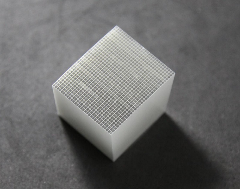
Figure 1. LYSO(Ce) Arrays
Product Introduction:
yttrium silicate lutetium crystal array structure
This product is a lutetium yttrium silicate crystal array, a common medical radiation imaging element. The structure and fabrication process of the lutetium yttrium silicate crystal array are as follows:
Large cerium-doped lutetium yttrium silicate crystals are sawn into small rectangular strips.
These cut small crystal strips are arranged closely on a plane, each small crystal strip being an independent unit, called a "pixel". The arrangement of these small crystal strips is an array.
Between each small crystal, there is a thin optical reflective layer, and all five sides of the array (except the light-emitting surface) are covered with optical reflective layers. The reflective layer material can be 3M ESR or titanium dioxide. Sometimes, an aluminum foil reflective layer (made of aluminum) may be added upon customer request. The thickness of the reflective layer typically ranges from 0.06mm to 0.5mm, with actual specifications varying depending on the customer. The primary function of these reflective layers is to bond the small pieces of yttrium lutetium silicate crystals together, and the secondary function is to confine the light within the crystal pixels and guide it to the light-emitting port. The reflective layer is applied to the crystal surface only physically, without introducing new chemical components.
%20Arrays%20for%20PET-jpg.jpg)
Figure 2. The structure of the lutetium yttrium silicate crystal array is shown in the schematic diagram above. The large cube in the diagram represents the lutetium yttrium silicate crystal array, and each small blue square represents a cerium-doped lutetium yttrium silicate crystal (i.e., a "pixel"); the white part represents the optical reflective layer.
Cerium-doped yttrium silicate crystals
Cerium-doped lutetium yttrium silicate crystals, with the simplified chemical formula LYSO4: Ce, are a scintillation crystal material. This product is prepared by a chemical reaction and crystallization of cerium-doped lutetium oxide, yttrium oxide, and silicon dioxide in a high-temperature growth furnace, typically using the Czochralski method. The elements lutetium and yttrium exist in this product as inseparable crystals. Cerium-doped lutetium yttrium silicate crystals in… Strong fluorescence can be produced under the action of high-energy rays such as X- rays and gamma rays , which is suitable for the field of radiation detection.
Cerium-doped yttrium lutetium silicate ( LYSO: Ce ) crystals are characterized by high light yield, fast light decay time, and high density. They are non-hygroscopic and have good detection efficiency for gamma rays, making them a commonly used inorganic scintillation crystal material.
yttrium silicate lutetium crystal array
In the yttrium silicate lutetium array, the LYSO: Ce crystal is cut into multiple cuboid-shaped small crystal blocks and arranged in an array. Each small crystal block is defined as a pixel, and optical reflective layers are applied to the outer five sides of the array between each small crystal block.
When a high-energy particle (such as a gamma photon) strikes a crystal pixel, the pixel emits fluorescence due to the properties of lutetium yttrium silicate crystals. The reflective coating acts as a mirror, reflecting the fluorescence back into the crystal pixel, preventing crosstalk between pixels, and guiding the fluorescence to the end of the array. During use, electronic components (not contained in the product itself) are attached to the end of the array, and the light is captured by these components. The electronic components read the light signal from each crystal pixel , reconstructing information such as the position, time, and energy of the high-energy particle striking the array, thereby enabling imaging and other functions.
yttrium lutetium silicate ( LYSO: Ce ) arrays, which include PET, TOF-PET, and other medical imaging technologies, are currently the most widely used medical radiation imaging elements.
Working principle of LYSO(Ce) Scintillation Arrays in PET:
Yttrium lutetium silicate crystal arrays are commonly used components in medical radiation imaging, such as PET (positron emission tomography). By using this product in PET technology, it is possible to generate a map of the distribution of metabolic activity in a patient's body.
1. A tracer is injected into the patient's body. After the tracer accumulates in a specific tissue (such as a tumor lesion), the nuclide carried by the tracer emits a positron, which, through positron annihilation, produces a gamma photon.
2. Each small crystal in the yttrium lutetium silicate crystal array is a crystal pixel. When a gamma photon passes through the reflective layer and strikes a crystal "pixel" in the array, the crystal immediately absorbs the energy and then emits a weak blue fluorescence of a specific wavelength.
Because of the optical reflective layer surrounding the crystal pixel, the blue fluorescence emitted by each pixel is confined within its own crystal pixel and guided to the light-emitting surface of the array.
Electronic components (not included in this product) are attached to the light-emitting surface of the array during use. These components capture the light signal ( i.e., the blue fluorescence emitted by the crystal ) from each crystal pixel and convert it into an electrical signal. Because the array is pixelated, each pixel is an independent unit, so the host computer can immediately determine which specific pixel is emitting fluorescence.
Ultimately, by reading the electrical signal of each pixel, the computer can reconstruct information such as the location, time, and energy at which high-energy particles hit the array, thus forming an image that can be used for medical imaging (such as PET).
Production Process of LYSO(Ce) Scintillation Arrays
(1) Material preparation and crystal growth
Raw materials such as lutetium oxide, yttrium oxide, silicon dioxide, and cerium oxide are mixed in a specific ratio, placed in a crucible, and then placed in a single crystal growth furnace. Crystal growth is carried out using the Czochralski method: the raw materials are melted and undergo a high-temperature chemical reaction in an inert gas environment above 2000°C. Then, the crystal is pulled upwards using a pulling rod to grow a cerium-doped lutetium yttrium silicate (LYSO:Ce) crystal blank.
(2) Blank inspection and preliminary processing
After the crystal blanks have been grown, they are inspected for quality and confirmed to be qualified. Then, according to the overall dimensions of the array design, the large crystal blanks are cut into crystal bricks that are easy to process later.
(3) Crystal preparation and precision machining
The crystal bricks are then further precision-cut into tiny crystal strips with cross-sections consistent with the size of a single pixel, as required by the design. Subsequently, each facet of these crystal strips, especially the end facet of the light-emitting surface, is polished.
(4) Array integration and coating of the reflective layer
Numerous polished LYSO: Ce crystal strips are arranged in a pre-defined array. Between each strip, a high-reflectivity material is filled or sandwiched as an optical isolation layer, including 3M ESR reflective layers and titanium dioxide reflective layers. Sometimes, an aluminum foil reflective layer (made of aluminum) may be added upon customer request. This step is crucial for forming the pixelated array; the reflective layer effectively confines the fluorescence emitted by each crystal strip (i.e., each pixel) within the strip, preventing light crosstalk and ensuring spatial resolution. The reflective layer is physically attached between the small crystal strips and does not introduce new chemical components.
(5) Array coating
After the array is integrated, an optical reflective film is uniformly coated on the five outer surfaces of the array (except for the light-emitting surface). This film effectively reflects and focuses the fluorescence emitted by the crystal strips onto the uncoated light-emitting surface. The process of coating the reflective layer on the outer surface of the array is also a physical process and does not generate new chemical components.
Application areas of LYSO(Ce) Scintillation Arrays
Lutetium yttrium silicate crystal arrays are widely used in medical imaging and nuclear medicine, serving as common detection elements in imaging equipment such as PET (positron emission tomography) and SPECT (single-photon emission computed tomography) . These arrays can efficiently and accurately convert and locate gamma rays generated by positron annihilation within the body into optical signals, thereby reconstructing three-dimensional images of internal physiological metabolic activities. This plays an indispensable and crucial role in fields such as early cancer diagnosis, brain function research, and cardiac disease assessment.
2. GAGG(Ce) array for PET:
This product consists of cerium-doped gadolinium aluminum gallium garnet crystals and a reflective layer covering the surface of the cerium-doped gadolinium aluminum gallium garnet crystals. The cerium-doped gadolinium aluminum gallium garnet crystals are made into crystal strips, which are closely arranged on a plane and separated by the reflective layer. The reflective layer prevents light crosstalk and concentrates the light into the detector. The five faces of the array are covered by reflectors.
Cerium-doped gadolinium aluminum gallium garnet crystal, simplified chemical formula: Ce: GAGG (molecular formula: Ce: Gd3Al2Ga3O12). The cerium-doped gadolinium aluminum gallium garnet crystal is a crystalline material (main components: gadolinium 49.5%, aluminum: 5.7%, oxygen: 22.6%, gallium: 22%, cerium: 0.2%).
The reflective layer can be made of 3M ESR (polyethylene terephthalate) or of titanium dioxide (mixed with resin or plastic). Sometimes, an aluminum foil reflective layer (made of aluminum) is added upon customer request.
Product Images
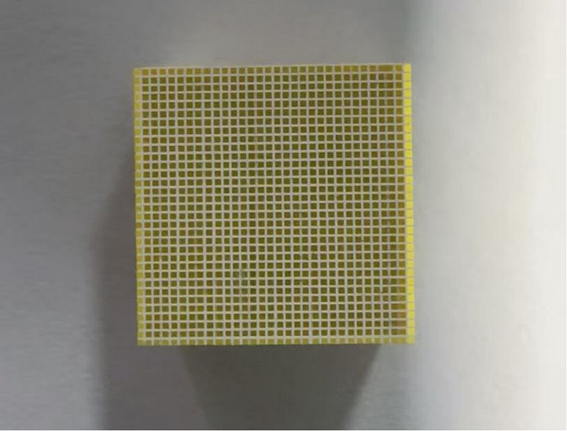
Figure 3. GAGG(Ce) Arrays
Product Introduction:
Gadolinium aluminum gallium garnet (GAGG: Ce) crystal array structure
This product is a gadolinium aluminum gallium garnet crystal array, a common medical radiation imaging element. The structure and fabrication process of the gadolinium aluminum gallium garnet crystal array are as follows:
The large cerium-doped gadolinium aluminum gallium garnet crystal blanks are sawn into small rectangular crystal strips.
These cut small crystal strips are arranged closely on a plane, each small crystal strip being an independent unit, called a "pixel". The arrangement of these small crystal strips is an array.
Between each small crystal, there is a thin optical reflective layer, and all five sides of the array (except the light-emitting surface) are covered with optical reflective layers. The reflective layer material can be 3M ESR, titanium dioxide, or sometimes an aluminum foil reflective layer (composed of aluminum) may be added upon customer request. The reflective layer thickness typically ranges from 0.06mm to 0.5mm, with actual specifications varying depending on the customer. The primary function of these reflective layers is to bond the small pieces of cerium-doped gadolinium aluminum gallium garnet crystals together; the secondary function is to confine the light within the crystal pixel and guide it to the light-emitting port. The reflective layer is applied to the crystal surface only physically, without introducing new chemical components.
 Arrays for PET.jpg)
Figure 4. The structure of a gadolinium aluminum gallium garnet crystal array is shown in the schematic diagram above. The large cube in the diagram is the gadolinium aluminum gallium garnet crystal array, and one of the small yellow squares represents a cerium-doped gadolinium aluminum gallium garnet crystal (i.e., a "pixel"); the white part represents the optical reflective layer.
Cerium-doped gadolinium aluminum gallium garnet crystals
Cerium-doped gadolinium aluminum gallium garnet crystal, with the simplified chemical formula Ce: GAGG, is a commonly used scintillation crystal that fluoresces under the influence of X-rays, gamma rays, etc. Ce: GAGG crystals are characterized by high light yield and high energy resolution, as well as high density, no self-radiation, and non -hygroscopicity. Due to their excellent temporal and spatial resolution, they are widely used in container inspection and security checks, medical SPECT imaging, and medical PET imaging.
Cerium-doped gadolinium aluminum gallium garnet crystals are prepared by thoroughly mixing gadolinium oxide, aluminum oxide, and gallium oxide raw materials, then incorporating cerium oxide raw materials, placing the mixture in a crystal growth furnace, where a chemical reaction occurs at high temperature, and then growing the crystal using the Czochralski method. Elements gadolinium and gallium exist in a stable, inseparable form within the crystal.
Gadolinium aluminum gallium garnet crystal array
In a gadolinium aluminum gallium garnet crystal array, the crystal is cut into multiple cuboid-shaped small crystal blocks, which are arranged in an array. Each small crystal block is defined as a pixel, and optical reflective layers are applied to the outer five sides of the array between each small crystal block.
When a high-energy particle, such as a gamma photon, strikes a crystal pixel, the cerium ions doped in the Ce: GAGG crystal cause the pixel to fluoresce under the radiation of the high-energy particle, with a peak fluorescence wavelength of approximately 520-530 nm . The encapsulated reflective layer acts as a mirror, reflecting the fluorescence back into the crystal pixel, preventing crosstalk between pixels, and guiding the fluorescence to the end of the array. During use, electronic components (not contained in the product itself) are attached to the end of the array, and the light is captured by these components. The electronic components read the light signal from each crystal pixel, reconstructing information such as the position, time, and energy of the high-energy particle striking the array, thereby achieving imaging and other functions.
Gadolinium aluminum gallium garnet crystal arrays include Medical imaging techniques such as PET and SPECT, which are also applicable to radiation detection security inspection equipment.
Working principle of GAGG(Ce) Scintillation Arrays in PET
Gadolinium aluminum gallium garnet (GAGaG) crystal arrays are widely used in medical radiation imaging, such as SPECT (single-photon emission computed tomography). By using this product to implement SPECT technology, medical imaging examinations such as myocardial perfusion imaging, bone imaging, and thyroid scans can be performed. The following is the working principle of GGAGaG crystal arrays in SPECT medical imaging:
1. A photon-emitting isotope will be injected into the patient's body. The isotope directly emits a single gamma photon.
2. Each small crystal in a cerium-doped gadolinium aluminum gallium garnet (GAGaG) crystal array is a crystal pixel. When a gamma photon passes through the mechanical collimator and array reflective layer of the SPECT detector, it strikes a specific crystal "pixel" in the array . During SPECT, the energy of the gamma photons emitted by the nuclide injected into the patient is generally not high, but because the cerium-doped GADGaG crystal has a high density and high blocking ability, the crystal can effectively capture and absorb the energy of the gamma photons, and then the crystal emits fluorescence at 520-530 nm.
Because of the optical reflective layer surrounding the crystal pixel, the fluorescence emitted by each pixel is confined within its own crystal pixel and guided to the light-emitting surface of the array.
Electronic components (not included in this product) are attached to the light-emitting surface of the array during use. These components capture the light signal (i.e., the blue fluorescence emitted by the crystal) from each crystal pixel and convert it into an electrical signal. Because the array is pixelated, each pixel is an independent unit, so the host computer can immediately determine which specific pixel is emitting fluorescence.
Ultimately, by reading the electrical signal of each pixel, the computer can reconstruct information such as the location, time, and energy of the high-energy particles hitting the array, thereby obtaining a three-dimensional distribution image of the nuclide in the patient's body , forming an image that can be used for medical imaging (such as SPECT ).
Production Process
(1) Material preparation and crystal growth
Raw materials such as gadolinium oxide, aluminum oxide, gallium oxide, and cerium oxide are mixed in a specific ratio, placed in a crucible, and then placed in a single crystal growth furnace. Crystal growth is performed using the Czochralski method: in a high-temperature, inert gas-protected environment of approximately 1850°C, the raw materials are melted to undergo a high-temperature chemical reaction to form a homogeneous melt. The melt is then guided by a pulling rod, ultimately growing a cerium-doped gadolinium aluminum gallium garnet (Ce:GAGG) crystal blank. Elements gadolinium and gallium exist in a stable and inseparable form within the crystal.
(2) Blank inspection and preliminary processing
After the crystal blanks have been grown, they are inspected for quality and confirmed to be qualified. Then, according to the overall dimensions of the array design, the large crystal blanks are cut into crystal bricks that are easy to process later.
(3) Crystal preparation and precision machining
The crystal bricks are then further precision-cut into tiny crystal strips with cross-sections consistent with the size of a single pixel, as required by the design. Subsequently, each facet of these crystal strips, especially the end facet of the light-emitting surface, is polished.
(4) Array integration and coating of reflective layer
Numerous polished Ce:GAGG crystal strips are arranged in a pre-defined array. Between each strip, a high-reflectivity material is filled or sandwiched as an optical isolation layer, including 3M ESR reflective layers and titanium dioxide reflective layers. Sometimes, an aluminum foil reflective layer (composed of aluminum) is added according to customer requirements. This step is crucial for forming the pixelated array; the reflective layer effectively confines the fluorescence emitted by each crystal strip (i.e., each pixel) within the strip, preventing light crosstalk and ensuring spatial resolution. The reflective layer is physically attached between the small crystal strips and does not introduce new chemical components.
(5) Array coating
After the array is integrated, an optical reflective film is uniformly coated on the five outer surfaces of the array (except for the light-emitting surface). This film effectively reflects and focuses the fluorescence emitted by the crystal strips onto the uncoated light-emitting surface. The process of coating the reflective layer on the outer surface of the array is also a physical process and does not generate new chemical components.
Application areas:
Gadolinium aluminum gallium garnet (GAGaG) crystal arrays are widely used in medical imaging and nuclear medicine, serving as common detection elements in imaging equipment such as PET (positron emission tomography) and SPECT (single-photon emission computed tomography) . In SPECT applications, GGAGaG crystal arrays can efficiently and accurately convert and locate gamma photons generated by nuclides within the patient's body into optical signals, thereby generating a three-dimensional distribution image of the nuclide within the patient's body . This enables myocardial perfusion imaging, bone imaging, thyroid scans, and visual examination of cerebral blood flow.
Cerium-doped lanthanum bromide/LaBr3(Ce) scintillator arrays with potential applications in the TOF-PET field:
A LaBr3(Ce) pixelated scintillation array consists of numerous cubic LaBr3 (lanthanum bromide) crystals arranged linearly or in a two-dimensional manner, along with optical reflectors between the crystals. Cerium-doped lanthanum bromide crystals, abbreviated as LaBr3(Ce), possess characteristics such as high light output, excellent energy resolution, and fast decay time (typically 16-25 ns), making them highly promising for gamma-ray spectrometers and radiation imaging applications requiring high time resolution, such as medical imaging TOF-PET (Time-of-Flight Positron Emission Tomography), an advanced PET imaging technique that improves image quality by measuring the difference in arrival times of the two photons produced during positron annihilation.
Tags: PET scintillator