
Instant Guide-Important Specifications for Ultrafast Optics
Ultrafast lasers, also interchangeably called ultrashort lasers, defined as pulsed lasers with pulse width of picoseconds or less than 1 picosecond (1ps=1x10^-12s), have been applied and are showing prospects in areas like laser drilling/cutting, micromachining, semiconductor processing, imaging (You can view more in our previous blog The Development and Applications of Ultrafast Laser).
In the application of ultrafast lasers, the primary purpose is often to direct the laser pulse with the highest fluence and narrowest pulse width to the target. Unlike the standard nanosecond pulsed lasers, ultrafast lasers with pulse widths in the picosecond and femtosecond range bring the challenge of extraordinary peak power; therefore, leading-edge ultrafast optics are indispensable. Learning to interpret the specifications of ultrafast optics is necessary to avoid failure of your ultrafast laser systems. In this blog, we break down the five critical parameters you should evaluate before purchasing ultrafast optics, such as mirrors, lenses, windows, or dispersion compensation elements. You need to consider the following before purchasing ultrafast optics:
1. The Wavelength Range
2. Dispersion
3. Dispersion Compensation
4. Average Power, Peak Power, Fluence
5. Laser Induced Damage Threshold
6. Angle of Incidence
7. Polarization
8. Surface Specification
1. Wavelength Range
The process in which ultrashort laser pulses are generated is, in essence Fourier transformation. To obtain short pulse durations, the wavelength spectrum of the ultrafast laser has to be very broad. Not like most laser sources, which have a narrow output wavelength and therefore can be considered to be monochromatic. In fact, there is a mathematical equation relating the pulse duration and wavelength bandwidth of ultrafast lasers: Δt*Δv≥ 4π/1.
The relationship between wavelength range and pulse duration is further illustrated and explained in another Shalom EO’s blog, Learning About The Physics of Ultrafast Lasers.
Getting back to the topic, because ultrafast lasers have an extensive wavelength range, the ultrafast optics you choose must be optimized for the wavelength range, not just a single laser line.
The typical wavelength range of ultrafast lasers includes:
1. Near-infrared spectrum (700-1100nm): This is the primary wavelength range for ultrafast lasers and has a wide range of applications, including femtosecond lasers (e.g., Ti:Sapphire and ytterbium lasers), femtosecond spectroscopy, fiber optic communications, and life sciences.
2. Far-infrared spectrum (1100-2000nm): This wavelength range can be used in research fields such as high-resolution microscopy, transient optics, and molecular vibration.
3. Mid-infrared spectrum (2000-5000nm): This wavelength range is applicable to optical spectroscopy, infrared imaging, and material processing in manufacturing.
4. Far-infrared spectrum (>5000 nm): This wavelength range is suitable for optical imaging, infrared thermal imaging, and infrared spectral analysis.
- What you should mind: Always match the optic’s bandwidth with the laser’s output spectrum.
2. Dispersion
The most common concept of pulse duration (also called pulse width) is measured at the full width half maximum (FWHM) of the pulse, meaning the time between the points where the pulse's amplitude is half its peak value. As mentioned above, ultrafast lasers have pulse durations of picoseconds or less than 1 picosecond, which means the pulse durations of ultrafast lasers are miniature, ranging from dozens of picoseconds to only a few femtoseconds. The shorter the pulse duration, the more difficult it becomes to maintain the pulse shape, and the distortion gets more significant. For pulse durations shorter than 30fs, you should begin to take dispersion into consideration.
Due to the dispersive nature of optical media (glass substrate, optical coating, air), when ultrafast pulses propagate in the media, different wavelengths will have different refractive indices, causing pulse stretching, distortion, temporal chirp, and loss of peak power.
Dispersion is quantified using parameters like group delay dispersion (GDD), group velocity dispersion (GVD). In some demanding applications, you might even need third-order dispersion (TOD). Ultrafast optics are often specially optimized so they introduce minimal dispersion. The optic should not elongate or compress the pulse unintentionally. For instance, ultrafast optics are mostly made of fused silica, which is widely regarded as a low-dispersion material for ultrafast lasers
- What you should mind: if your pulse duration is shorter than 30fs, look for optics with small GDD. Oftentimes, the GDD value will be specified in fs^2. The lower and flatter the GDD curve across the spectrum, the better for maintaining pulse fidelities. Shalom EO offers high reflectance (R>99.9%), low GDD (±20fs2) dielectric mirrors for femtosecond lasers and various low GDD ultrafast optics like harmonic separators, ultrafast thin lenses and windows, ultrafast thin film polarizers, all are made of fused silica or C7980 substrates.
3. Dispersion Compensation
Sometimes, dispersions are deliberately exploited in the designs of ultrafast optics to realize active dispersion compensation or obtain pulse stretchers or pulse compressors, as means to restore the temporal pulse profile to purposefully expand/reduce the pulse width. Chirped mirrors are special dispersive mirrors designed for dispersion compensation. The chirped mirror contains coatings consisting of multiple thin films, and the thin films are of spatially varied thickness. The principle is to make longer wavelengths enter deeper into the coating, resulting in negative GDD that balances the detrimental positive dispersion produced during pulse propagation.
Pulse compressors and pulse stretches are ultrafast optics often used for chirped pulse amplification.
- What you should mind: If you want to actively restore the original pulse shape or modulate the pulse length, this usually means you are looking for optics that can introduce a certain magnitude of GDD. You should look for optics specified with the GDD value you want. Shalom EO offers off-the-shelf and custom chirped mirrors and chirped mirror pairs, where both standard GDD values and custom values are available. The GDD curves are tested using Shalom EO’s UltraFast Innovations GOBI white light interferometers.
The GDD curve of Shalom EO's dispersion compensation chirped mirrors:

4. Pulse Energies, Maximum Fluence, and Peak Power
Unlike continuous wave (CW) lasers, for which average power is the dominant metric, a more common parameter for ultrafast lasers is pulse energies, which is the amount of energy delivered in a single laser pulse; mathematically, pulse energies equals:
E(Pulse)=Average Power/Repetition Rate
Maximum fluence of your ultrafast laser is a useful parameter when you evaluate the laser-induced damage threshold. Maximum fluence equals E(pulse)/beam area. If your beam is a Gaussian beam, the result needs to be doubled.
Peak power is the highest power in a pulse; even the pulse energies of a single ultrafast pulse can seem tiny, but when combined with short pulse durations, the peak power of the ultrashort pulse can be extremely high. Peak power is more relevant when discussing nonlinear effects, but can also influence optical damage thresholds. The calculation formula for peak power is:
Peak Power=E(Pulse)/Pulse Duration
5. Laser Induced Damage Threshold (LIDT)
Ultrafast lasers can have gigantic peak power, even if the energies of a single pulse are low; when it is condensed into very short pulse durations, the peak power will be huge. The ultrafast pulsed lasers now available can have peak power reaching GW or even PW.
Therefore, the ultrafast optics must be able to withstand exposure to the incident laser beam. A universal specification that quatifies how will an optic can endure laser energies is the laser induced damage threshold (LIDT), for pulsed laser, it is defined as the maximum fluence per area that an optic can take before any unacceptable damage occurs at specific test conditions (for LIDTs of pulsed laser, the test condition usually include the wavelength, pulse width, and pulse repetition rate of the test laser). For example, LIDT of an ultrafast mirror is written as 2J/cm2@800nm, 100ps, 100Hz, which means the ultrafast mirror can withstand 2J laser fluence at maximum per centimeter square, when incident with a pulsed laser with wavelength 800nm, pulse duration 100ps, and repetition rate 100Hz.
Optics with insufficient LIDT can degrade or fail under these conditions. This is why you should look for optics with a higher damage threshold than the laser's expected fluence (J/cm² for pulsed lasers). However, LIDT is related to the wavelength and pulse duration. When the wavelength and pulse duration of your laser are different from the wavelength specified in the LIDT, you can not just compare the 2 values directly.
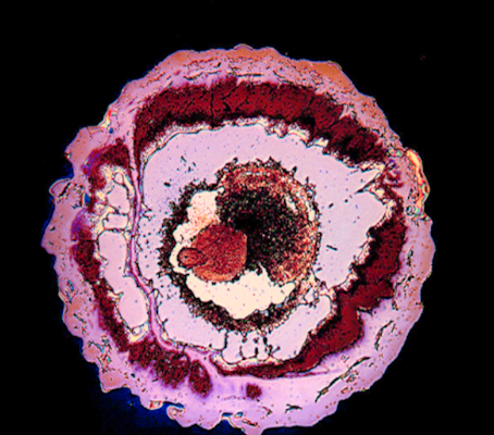
Figure 1. shows damage caused by lasers
The steps to use laser laser-induced damage threshold are as follows:
1. Calculate the maximum fluence of your laser: You should be clear whether your laser beam profile is Gaussian or flat-top. If the beam is a Gaussian beam, the intensity is highest at the center and falls off radially. The peak intensity is significantly higher than the average intensity. The peak fluence is 2*pulse energy/beam area. Don’t forget to times 2! Most ultrafast lasers—like Ti:Sapphire, Yb-doped fiber, or Er-doped systems—emit light with a Gaussian transverse intensity profile due to their resonator design and mode structure.
2. Scale specified LIDT to your wavelength and pulse duration: There is no accurate equation for scaling, a rule of thumb for rough calculation is (λ stands for wavelength, T stands for pulse duration, θ stands for repetition rate):
LIDT (your λ, your T, your θ) = Laser Induced Damage Threshold (specified λ, specified T, specified θ) x (your λ/specified λ) x (your T/specified T) x (your θ/specified θ)
Note: the rule should not be applied to circumstances with a large wavelength difference, for example, when the given wavelength is 1030nm and your wavelength is 355nm, the rule is no longer suitable. Laser-induced damage threshold is a very complex and sensitive issue; we suggest that you contact the engineers of Shalom EO to get professional advice.
3. Compare the 2 values. You should look for optics with a scaled LIDT that is higher than the maximum fluence of your ultrashort laser. However, this doesn't 100% guarantee that the optics are safe to use, as ultrafast laser pulses often deliver vast peak power, which might cause nonlinear optical effects and intense localized deposition energies, even at modest fluence. Optics with low LIDT can degrade, melt, or fracture under these conditions. Therefore, we strongly recommend that you get some professional advice if you are unsure about the LIDT.
6. Angle of Incidence (AOI)
The angle of incidence (AOI) is defined as the incoming (incident) ray of light, and the normal line (a line perpendicular) to the surface at the point where the light hits it. Most optical coatings, such as high reflection coatings and anti-reflection coatings, are sensitive to the angle of incidence, and ultrafast optics are not accepted. Ultrafast mirrors are set to be used at a designed angle of incidence or a range of incident angles.
- What to look for: Confirm that the optic’s reflectivities and dispersion characteristics are specified for your laser’s AOI.
7. Polarization:
Ultrafast lasers produce three main types of polarization: linear polarization, circular polarization, and elliptical polarization.
1. Linear Polarization: Linearly polarized light refers to light whose electric field vector oscillates only in a fixed direction. In ultrafast lasers, through specific design and control by using polarizing optics such as thin film polarizer, the electric field vector of the laser can be made to oscillate in a fixed direction, producing linearly polarized laser light.
2. Circular Polarization: Circularly polarized light refers to light whose electric field vector rotates at a constant rate in a plane perpendicular to the propagation direction. Ultrafast lasers can also produce circularly polarized laser light by adjusting optical path components to cause the electric field vector of the laser to rotate continuously during propagation.
3. Elliptically Polarized Light: Elliptically polarized light is a polarization state between linear and circular polarization, with its electric field vector following an elliptical path in a plane perpendicular to the propagation direction. Certain ultrafast lasers can also produce elliptically polarized laser light.
8. Reflectivities
Most ultrafast laser systems employ a large number of reflective optics. A typical ultrafast laser setup uses 10 or more reflective mirrors because they offer precise beam control, minimal dispersion, functional flexibilities, and help preserve both spatial and temporal beam quality—essential for femtosecond pulse applications. The more the number of reflective mirrors, the more unwanted optical loss due to reflection, as each reflection at each mirror adds up to the total optical loss. Therefore, mirrors with high reflectivities are preferred. Remember that reflectance of optics is dependent on wavelength, incident angle, and polarization.
- What to look for: Mirrors with high reflectivities at your laser’s application wavelength, incident angle, and polarization are ideal choices if you are looking for reflectors.
Surface Profile-Surface Quality and Surface Flatness
Surface quality, according to the MIL-PRF-13830B, surface quality is usually evaluated using scratch/dig. Optics with large scratch/dig imply lower surface smoothness, leading to high scatter loss. Also, one must discriminate between the surface quality of optical substrates and the surface quality after coating. Controlling the surface quality after optical coating is much more difficult, as during the coating process, particulate contamination, plasma damage, or handling defects might introduce scratches or pits.
Surface flatness is the degree of deviation between a sample's surface and its ideal surface. This concept can be quantified using two parameters: PV and RMS. PV, or Peak to Valley, represents the difference between the highest and lowest points on a surface; while RMS, or Root Mean Square, is a root mean square value, which is typically smaller than PV. In the profession, PV is commonly used to describe optical components with simple surface shapes. Surface flatness is usually measured using an interferometer (click here to learn more about interferometer) and is expressed relative to a standard light wavelength, most often 633 nm (HeNe laser). Surface flatness are specified in fractions of a wavelength of light (λ), like λ/4, λ/10, at the interferometer’s wavelength. For example, a surface flatness of λ/10 measured using a 633nm interferometer means the surface deviates no more than 1/10 λ = 1/10 x 633nm =63.3nm from a perfect plane. Hangzhou Shalom EO employs Zygo interferometers to conduct stringent optical testing of our ultrafast optics.
- What to look for: ultrafast optics typically require a surface flatness of λ/10@633nm or better, which Shalom EO is capable of achieving.
You can also view another series of Shalom EO's blogs, where the specifications of common optics are comprehensively explained:
1. Understanding Optical Specifications-Geometric Specifications
2. Understanding Optical Specifications: Surface Specifications
3. Understanding Optical Material Properties
Related Articles
Related Products

Tags: Instant Guide-Important Specifications for Ultrafast Optics